ARDUINO – КОНТРОЛЛЕР СИСТЕМЫ ОСВЕЩЕНИЯ
С WEB-СЕРВЕРОМ НА ORANGE PI ZERO
ARDUINO - CONTROLLER OF LIGHTING SYSTEMS
WITH WEB-SERVER ON ORANGE PI ZERO
Предлагаю описание простого и недорогого устройства для управления системой освещения на 6 групп света
через звонковые (без фиксации, подпружиненные) выключатели с возможностью управления с компьютера и/или смартфона
через локальную компьютерную сеть без внешнего подключения в Интернет. Роль локального WEB-сервера, обеспечивающего
WEB-интерфейс будет играть Linux микрокомьютер, например Orange Pi Zero, NanoPi, Raspberry Pi или любой другой аналогичный.
В такой схеме каждая группа света может управляться с любого количества выключателей, которые соединяются паралельно, чем решается проблема проходных выключателей и обесечивается возможность дистанционного управления через сеть со смартфона или компьютера.
Это устройство вы можете собрать самостоятельно следуя этой инструкции. Предполагается что ви обладаете навыками работы с напряжением 220В, макетирования и программирования микроконтроллеров Arduino.
Все компоненты, необходимые для сборки устройства, можно приобрести в интернет-магазине, например arduino.ua.
I offer a description of a simple and inexpensive device for controlling a lighting system for 6 groups of light
through bell (spring-loaded) switches with the ability to control from a computer and / or smartphone
through a local computer network without external connection to the Internet.
The role of a local WEB server that provides
WEB - interface will play Linux microcomputer, for example Orange Pi Zero, NanoPi, Raspberry Pi or any other similar.
In such a scheme, each group of light can be controlled from any number switches, which are connected in parallel, what solves the problem of pass-through switches and provides an opportunity remote control via the network from a smartphone or computer.
This device can be assembled by yourself following this instruction. It is assumed that you have the skills to work with a voltage of 220V, prototyping and programming of microcontrollers Arduino.
All the components necessary for the assembly of the device can be purchased at the online store, arduino.ua.
Нам потребуются:
We will need:
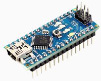
Микроконтроллер ARDUINO NANO
или любой другой подобный микроконтроллер,
например ARDUINO UNO, MICRO, MINI
Microcontroller ARDUINO NANO
or any other similar microcontroller,
for example ARDUINO UNO, MICRO, MINI
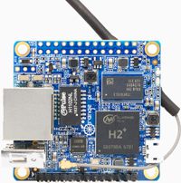
Микрокомпьютер Orange Pi Zero
или любой другой подобный, например Raspberry Pi.
Он будет выполнять роль локального WEB-сервера и необходим для
отображения WEB-страницы управления освещением.
или любой другой подобный, например Raspberry Pi.
Он будет выполнять роль локального WEB-сервера и необходим для
отображения WEB-страницы управления освещением.
Microcompute Orange Pi Zero
or any other similar, for example Raspberry Pi.
It will act as a local WEB server and is required for
displaying the WEB-page of lighting control.
or any other similar, for example Raspberry Pi.
It will act as a local WEB server and is required for
displaying the WEB-page of lighting control.
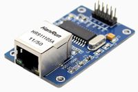
Ethernet module ENC28J60

Модуль питания TSP-05 220В - 5В 3Вт
или любой другой источник питания 5В/300mA для Arduino
или любой другой источник питания 5В/300mA для Arduino
Power Supply Module TSP-05 220В - 5В 3Вт
or any other 5V/300mA power supply for Arduino
or any other 5V/300mA power supply for Arduino
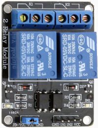
Три 2-х канальных модуля реле 5В 10А с опторазвязкой
Можно использовать и другие,
например 8-и канальные модули реле 5В 10А с опторазвязкой
или 1-о канальные модули реле 5В 10А с опторазвязкой
Можно использовать и другие,
например 8-и канальные модули реле 5В 10А с опторазвязкой
или 1-о канальные модули реле 5В 10А с опторазвязкой
Three 2-channel relay modules 5V 10A with opto-isolated
You can use other,
for example 8-channel relay modules 5V 10A with opto-isolation
or 1-channel relay modules 5V 10A with opto-isolation
You can use other,
for example 8-channel relay modules 5V 10A with opto-isolation
or 1-channel relay modules 5V 10A with opto-isolation
Звонковые выключатели:
Выключатели, у которых клавиша подпружинена и они
не имеют фиксированного положения.
Для управления группой света с нескольких точек,
выключатели можно соединять паралельно.
Выключатели, у которых клавиша подпружинена и они
не имеют фиксированного положения.
Для управления группой света с нескольких точек,
выключатели можно соединять паралельно.
Bell Switch (Push switch):
A push button is a momentary or non-latching switch which causes a
temporary change in the state of an electrical circuit only while the
temporary change in the state.
An spring returns the switch to its default position immediately
afterwards, restoring the initial circuit condition.
To control a group of light from several points, the switches
can be connected in parallel.
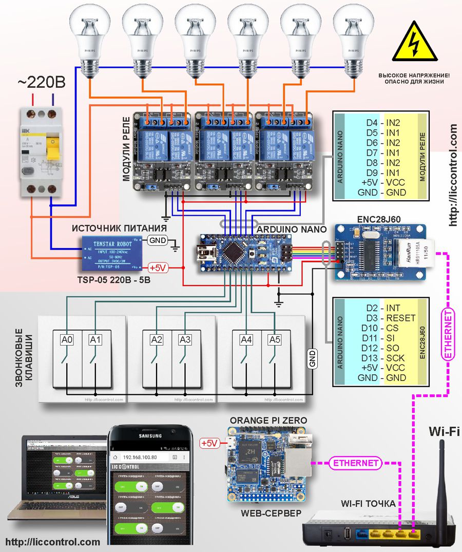
Принципиальная схема устройства:
Schematic diagram of the device:
Микроконтроллер ARDUINO NANO управляет силовыми реле, которые
коммутируют напряжение 220В для шести независимых групп освещения в которых могут использоваться
лампы любого типа. Максимальная коммутируемая мощность ограничивается мощностью применяемых реле.
Предлагаемые в описании релейные блоки рассчитаны на ток до 10А при использовании ламп накаливания,
это около 2 кВт на группу освещения. Если вы хотите обеспечить надежную и долговечную работу этих реле,
не превышайте мощность светильников с лампами накаливания больше 1 кВт на группу.
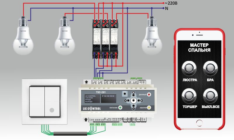
Для управления с настенных выключателей используются входа А0-А5. Режим управления - триггерный. Каждое следующее нажатие на клавишу выключателя меняет состояние выходного реле на обратное: ВКЛ<->ВЫКЛ. Благодаря такому подходу вы можете управлять одной группой света с любого количества точек. Для этого достаточно соединить необходимое количество выключателей параллельно. Для соединения выключателей не обязательно использовать силовой электропровод или кабель, можно использовать любой сигнальный провод, например FTP. Для иллюстрации такого принципа управления освещением, ниже приведена анимированная схема управления. Кнопки выключателя и кнопки смартфона кликабельны - можете кликнуть на них мышкой, чтобы увидеть, как работает система.
Для управления с настенных выключателей используются входа А0-А5. Режим управления - триггерный. Каждое следующее нажатие на клавишу выключателя меняет состояние выходного реле на обратное: ВКЛ<->ВЫКЛ. Благодаря такому подходу вы можете управлять одной группой света с любого количества точек. Для этого достаточно соединить необходимое количество выключателей параллельно. Для соединения выключателей не обязательно использовать силовой электропровод или кабель, можно использовать любой сигнальный провод, например FTP. Для иллюстрации такого принципа управления освещением, ниже приведена анимированная схема управления. Кнопки выключателя и кнопки смартфона кликабельны - можете кликнуть на них мышкой, чтобы увидеть, как работает система.
The ARDUINO NANO microcontroller controls power relays that
switch voltage 220V for six independent lighting groups in which can be used
lamps of any type. The maximum switched power is limited by the power of the applied relays.
The relay blocks offered in the description are designed for current up to 10A when using incandescent lamps,
this is about 2 kW per lighting group. If you want to ensure the reliable and durable operation of these relays,
Do not exceed the power of lamps with incandescent lamps greater than 1 kW per group.
Inputs A0 to A5 are used to control the wall switches. The control mode is triggered. Each subsequent pressing of the switch key changes the status of the output relay to the opposite: ON <-> OFF. Thanks to this approach, you can control one group of light from any number of points. To do this, enough connect the required number of switches in parallel. For connection of switches it is not necessary to use power cable or cable, you can use any signal wire, for example FTP. To illustrate this principle of lighting control, the following is an animated control scheme. The buttons of the switch and the buttons of the smartphone are clickable - you can click on them to see how the system works.
Inputs A0 to A5 are used to control the wall switches. The control mode is triggered. Each subsequent pressing of the switch key changes the status of the output relay to the opposite: ON <-> OFF. Thanks to this approach, you can control one group of light from any number of points. To do this, enough connect the required number of switches in parallel. For connection of switches it is not necessary to use power cable or cable, you can use any signal wire, for example FTP. To illustrate this principle of lighting control, the following is an animated control scheme. The buttons of the switch and the buttons of the smartphone are clickable - you can click on them to see how the system works.


Для управления силовыми реле, на контроллере ARDUINO NANO используются цифровые выхода D4,D5,D5,D7,D8,D9,
которые соединяются с соответствующими входами на релейных модулях IN1, IN2.
Для питания схемы следует использовать источник +5В, который обеспечит ток не менее 250-300 мА. Если мощность источника питания будет недостаточна, сетевой модуль ENC28J60 может работать не стабильно.
Для питания схемы следует использовать источник +5В, который обеспечит ток не менее 250-300 мА. Если мощность источника питания будет недостаточна, сетевой модуль ENC28J60 может работать не стабильно.
To control power relays, the ARDUINO NANO controller uses the digital outputs D4, D5, D5, D7, D8, D9,
which are connected to the corresponding inputs on the relay modules IN1, IN2.
To supply the circuit, use a + 5V source that will provide a current of at least 250-300 mA. If the power supply capacity is insufficient, the network module ENC28J60 may not work stably.
To supply the circuit, use a + 5V source that will provide a current of at least 250-300 mA. If the power supply capacity is insufficient, the network module ENC28J60 may not work stably.
Алгоритм работы прораммы.
The algorithm of the program.
Программа, которая будет загружена в контроллер ARDUINO NANO содержит три основных логических блока,
которые выполняются циклически в бесконечном цикле loop().
Первый блок программы ReadInput() отвечает за периодический опрос состояния входов на предмет обнаружения момента нажатия на клавишу выключателя. В момент нажатия на клавишу на соответствующий вход контроллера подается напряжение +5В что интерпретируется контроллером как логическая единица. Отсутствие напряжения на входе означает логический ноль.
Второй блок программы EthernetUpdate() обрабатывает GET запросы с WEB-страничек на включение и выключение групп света а также передает состояние (ВКЛ/ВЫКЛ) групп света для отображения на WEB-страничке в смартфоне или компьютере.
Третий блок программы SetOutput() управляет выходами контроллера. В этом блоке появление логической единицы на входе контроллера переводит состояние соответствующего выхода в обратное состояние. Т.е., если выход был в состоянии ВЫКЛ, он перейдет в состояние ВКЛ и наоборот.
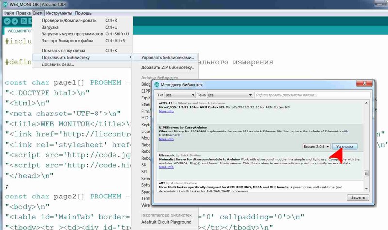
Что бы запрограммировать ARDUINO UNO вам потребуется библиотека UIPEthernet. В Arduino IDE 1.8.4 ее можно установить через меню «Скетч»-«Подключить библиотеку» - «Управлять библиотеками» - «Менеджер библиотек» - UIPEthernet.
Также можно скачать библиотеку с GitHub по адресу https://github.com/UIPEthernet/UIPEthernet.
![IDE Arduino 1.8.4]()
Первый блок программы ReadInput() отвечает за периодический опрос состояния входов на предмет обнаружения момента нажатия на клавишу выключателя. В момент нажатия на клавишу на соответствующий вход контроллера подается напряжение +5В что интерпретируется контроллером как логическая единица. Отсутствие напряжения на входе означает логический ноль.
Второй блок программы EthernetUpdate() обрабатывает GET запросы с WEB-страничек на включение и выключение групп света а также передает состояние (ВКЛ/ВЫКЛ) групп света для отображения на WEB-страничке в смартфоне или компьютере.
Третий блок программы SetOutput() управляет выходами контроллера. В этом блоке появление логической единицы на входе контроллера переводит состояние соответствующего выхода в обратное состояние. Т.е., если выход был в состоянии ВЫКЛ, он перейдет в состояние ВКЛ и наоборот.
Что бы запрограммировать ARDUINO UNO вам потребуется библиотека UIPEthernet. В Arduino IDE 1.8.4 ее можно установить через меню «Скетч»-«Подключить библиотеку» - «Управлять библиотеками» - «Менеджер библиотек» - UIPEthernet.
Также можно скачать библиотеку с GitHub по адресу https://github.com/UIPEthernet/UIPEthernet.
The program to be loaded into the ARDUINO NANO controller contains three basic logical blocks,
which are executed cyclically in an infinite loop loop ().
The first block of the program ReadInput () is responsible for periodic interrogation of the state of the inputs for detecting the moment of pressing on the button of the switch. At the moment the key is pressed, the corresponding input of the controller is supplied with a voltage of + 5V which is interpreted by the controller as a logical unit. The absence of input voltage means a logical zero.
The second block of the program EthernetUpdate () processes GET requests from WEB-pages to include and switching off groups of light and also transmits the state (ON / OFF) of groups of light for display on WEB-page in a smartphone or computer.
The third block of the program SetOutput () controls the outputs of the controller. In this block, the appearance of a logical the unit at the controller input switches the state of the corresponding output to the reverse state. Ie, if the output was OFF, it will go ON and vice versa.
To program the ARDUINO UNO you need the UIPEthernet library. In Arduino IDE 1.8.4 it can be installed via the menu "Sketch" - "Connect the library" - "Manage libraries" - "Library Manager" - UIPEthernet.
You can also download the library from GitHub at https://github.com/UIPEthernet/UIPEthernet.
![IDE Arduino 1.8.4]()
The first block of the program ReadInput () is responsible for periodic interrogation of the state of the inputs for detecting the moment of pressing on the button of the switch. At the moment the key is pressed, the corresponding input of the controller is supplied with a voltage of + 5V which is interpreted by the controller as a logical unit. The absence of input voltage means a logical zero.
The second block of the program EthernetUpdate () processes GET requests from WEB-pages to include and switching off groups of light and also transmits the state (ON / OFF) of groups of light for display on WEB-page in a smartphone or computer.
The third block of the program SetOutput () controls the outputs of the controller. In this block, the appearance of a logical the unit at the controller input switches the state of the corresponding output to the reverse state. Ie, if the output was OFF, it will go ON and vice versa.
To program the ARDUINO UNO you need the UIPEthernet library. In Arduino IDE 1.8.4 it can be installed via the menu "Sketch" - "Connect the library" - "Manage libraries" - "Library Manager" - UIPEthernet.
You can also download the library from GitHub at https://github.com/UIPEthernet/UIPEthernet.
Ниже приведен листинг программы для контроллера ARDUINO NANO.
Below is a listing of the program for the controller ARDUINO NANO.
/*
КОНТРОЛЛЕР ОСВЕЩЕНИЯ С WEB-ИНТЕРФЕЙСОМ НА ARDUINO UNO + ENC28J60
Разработка - LIC CONTROL  http://liccontrol.com
Схема: http://liccontrol.com/article19.htm
Соединение Arduino Nano <-> ENC28J60
    D2  <-> INT
    D3  <-> RESET
    D10 <-> CS
    D11 <-> SI (ST)
    D12 <-> SO
    D13 <-> SCK
Входа для подключения выключателей: A0,A1,A2,A3,A4,A5
Выхода для подключения реле: 4,5,6,7,8,9
*/

//Закомментируйте эту строку, если прошивка
//контроллера не поддерживает Watchdog
#include <avr/wdt.h>
#include <UIPEthernet.h>

const int LedPin = 13;
//Входа для подключения выключателей
const int pins_in_count=6;
int pins_in[pins_in_count]  = {A0,A1,A2,A3,A4,A5};

//Выхода для подключения реле, управляющих группами света
const int pins_out_count=6;
int pins_out[pins_out_count] = {4,5,6,7,8,9};

//Массив для хранения текщего состояния группы света
int pins_state[pins_in_count];
//Массив для хранения предыдущего состояния группы света
int pins_old_state[pins_in_count];

//Установите false для отключения вывода отладочной информации
boolean myDebug = true;
//MAC-адрес
static uint8_t mac[6] = {0xBE, 0x9F, 0x18, 0x00, 0x00, 0x00};
static uint16_t port = 80;
String result="";

//Укажите подходящий адрес для контроллера в вашей сети
IPAddress ip(192, 168, 100, 80);
EthernetServer server(80);
//Укажите IP-адрес WEB-сервера (OrangePi, RaspberryPi)
const char server_ip[] PROGMEM = "http://192.168.100.125";
const char page1[] PROGMEM =
"<!DOCTYPE html>\n<html dir='ltr' lang='ru'>\n"
"<head lang='en'>\n<meta charset='UTF-8'>\n"
"<title>УПРАВЛЕНИЕ ОСВЕЩЕНИЕМ</title>\n"
"</head><body>\n"
"<div id='heder'></div>\n<div id='blank'></div>\n"
"<div id='main'><h3>Нет соединения с WEB сервером по адресу: @!</div>\n"
"<link rel='stylesheet' href='@/static/css/style.css' type='text/css'>\n"
"<script src='@/static/js/jquery-3.1.1.min.js'></script>\n"
"<script type='text/javascript' src='@/static/js/index.js'> </script>\n"
"</body></html>\n";

const char page2[] PROGMEM =
"HTTP/1.1 200 OK\n"
"Content-Type: text/html\n"
"Pragma: no-cache\n"
"Connection: close\r\n\r\n";

//Отправляем в сеть данные, которые хранятся в PROGMEM
void printProgStr(EthernetClient client, const char * str, const char * str1) {
char c,c1;
  if (!str) return;
  while ((c = pgm_read_byte(str++))) {
    if (c=='@') {
      for (int k = 0; k < strlen_P(server_ip); k++)  {
          c =  pgm_read_byte_near(server_ip + k);
          client.print(c);
      }
    } else
    client.print(c);
  }
}

//Перезапускаем Ethernet модуль ENC28J60
void resetENC28J60() {
  digitalWrite(3, LOW);
  delay(200);
  digitalWrite(3, HIGH);
  delay(50);
}

//Опрашиваем состояния входов на предмет
//обнаружения нажатия клавиши выключателя
void ReadInput() {
  unsigned long PressTime = 0;
  int d=0;
  for (int i=0; i<pins_in_count; i++) {
    d = digitalRead(pins_in[i]);
    if (d != pins_old_state[i]) {
      PressTime = millis();
      while ((d != pins_old_state[i]) and ((millis()-PressTime)<50)) {
        d = digitalRead(pins_in[i]);
        delay(10);
      }
      if (not (millis()-PressTime)<50) {
        if (d<1) {
          pins_state[i] = not pins_state[i];
          if (myDebug) {
            Serial.println("RELE("+String(i)+"), STATE="+String(pins_state[i]));
          }
        }
      }
    }
    pins_old_state[i] = d;
  }
}

//Устанавливаем выхода, которые управляют реле
void SetOutput() {
  for (int i=0;i<pins_out_count;i++) {
     digitalWrite(pins_out[i], pins_state[i]);
  }
}

//Формируем JSON строку состояния выходов (реле)
//для передачи в WEB-браузер
String StringInput() {
  String _return = "[";
  for (int i=0; i<pins_in_count; i++)
    _return = _return + String(int(pins_state[i]>0))+",";
  _return[_return.length()-1]=']';
  return _return;
}

//Начальные установки
void setup() {
  pinMode(LedPin, OUTPUT);
  digitalWrite(LedPin, HIGH);
  //Инициализация входов к которым подключены клавиши выключателей
  for (int i=0;i<pins_in_count;i++) {
    pinMode(pins_in[i], INPUT_PULLUP);
    pins_state[i] = 0;
  }
  //Инициализация выходов, которые управляют реле
  for (int i=0;i<pins_out_count;i++) {
     pinMode(pins_out[i], OUTPUT);
     digitalWrite(pins_out[i], LOW);
  }

  resetENC28J60();
  Ethernet.begin(mac, ip);
  server.begin();

  if (myDebug) {
    Serial.begin(9600);
    Serial.println("START PROGRAMM!");
    Serial.print("START SERVER AT:");
    Serial.println(Ethernet.localIP());
  }

  delay(10);
  //Закомментируйте строку ниже, если прошивка
  //контроллера не поддерживает Watchdog
  wdt_enable(WDTO_8S);
}

//Обработка GET запросов с WEB-страничек на вкл/вык групп света
void EthernetUpdate() {
  EthernetClient client = server.available();
  if (client) {
    result="";
    while (client.connected()) {
      if (client.available()) {
        char c = client.read();
        result+=c;
        if (c == '\n') {
          if (myDebug) Serial.print("Ethernet: "+result);
          if (result.indexOf("GET / HTTP/1.1")>=0) {
            printProgStr(client, page1, server_ip);
          } else
          if (result.indexOf("GET /ctrl/")>=0) {
            for (int i=0; i<pins_in_count; i++)
              if (result.indexOf("GET /ctrl/BT"+String(i))>=0)
                pins_state[i] = int(not pins_state[i]);
            printProgStr(client, page2, server_ip);
            client.println(StringInput());
          }
          client.flush();
          break;
        }
      }
    }
    delay(10);
    client.stop();
  }
}

void loop() {
  ReadInput();
  EthernetUpdate();
  SetOutput();
  //Закомментируйте строку ниже, если прошивка
  //контроллера не поддерживает Watchdog
  wdt_reset();
}
Для отладки не обязательно сразу собирать всю схему.
Для начала можно просто соединить Arduino Nano и ENC28J60 и через Arduino IDE загрузить программу в контроллер Arduino Nano.
(если вам нужны подробные инструкции как загрузить программу, воспользуйтесь
поиском в Google).
После загрузки программы в контроллер вы сможете протестировать считывание нажатий клавиш и передачу команд из WEB-браузера. Для этого в Arduino IDE откройте монитор порта (меню Tools -> Serial Monitor, Инструменты -> Монитор порта) и подайте по очереди +5В на ножки A0,A1,A2,A3,A4,A5.
В мониторе порта вы должны увидеть сообщения, например: RELE(0), STATE=1.
Для проверки Ethernet модуля, в адресной строке браузера введите адрес вашего контроллера, например как в листинге программы http://192.168.100.80
Если вы собрали схему правильно и модуль ENC28J60 рабочий,
в браузере вы увидите ответ: Нет соединения с WEB сервером по адресу: http://192.168.100.125!
При этом в мониторе порта должно появиться сообщение GET / HTTP/1.1
Если все работает нормально можно переходить к установке WEB сервера на Linux микрокомпьютере.
For debugging, you do not have to immediately compile the entire schema.
To begin with, you can simply connect the Arduino Nano and the ENC28J60 and load the program into the Arduino Nano controller via the Arduino IDE.
(if you need detailed instructions how to download the program, use
Google search ).
After loading the program into the controller, you can test the reading of keystrokes and transmission of commands from the WEB-browser. To do this, open the port monitor in the Arduino IDE (Tools -> Serial Monitor, Tools -> Port Monitor) and apply + 5V in turns to the feet A0, A1, A2, A3, A4, A5.
In the port monitor, you should see messages, for example: RELE (0), STATE = 1 .
To check the Ethernet module, enter the address of your controller in the address bar of the browser, for example as in the listing of the program http://192.168.100.80
If you have assembled the circuit correctly and the ENC28J60 module is working,
in the browser you will see the answer: There is no connection to the WEB server at: http://192.168.100.125!
At the same time, the message should appear in the port monitor GET / HTTP / 1.1
If everything works fine, you can proceed with installing the WEB server on a Linux microcomputer.
УСТАНОВКА WEB СЕРВЕРА НА ORANGE PI ZERO
INSTALLING WEB SERVER ON ORANGE PI ZERO
В данном примере используется микрокомпьютер Orange Pi Zero, как один из самых недорогих.
Могут быть использованы и другие микрокомпьютеры. В этом случае порядок установки может быть другим.
Сначала необходимо подготовить SD карточку с образом операционной системы Linux. Для Orange Pi Zero это Armbian. Для этого заходим на официальный сайт разработчика системы и скачиваем последнюю стабильную версию. Скачивается файл-архив размером примерно 220Мб. Вам необходимо распаковать его архиватором в любую удобную для вас папку. В результате вы получите папку с файлами, одним из которых будет файл с расширением .img. Это и есть файл с образом операционной системы, например Armbian_5.35_Orangepipc_Ubuntu_xenial_default_3.4.113.img. Теперь нам необходимо отформатировать карточку microSD в файловую систему FAT32 и с помощью программы Etcher скопировать на нее файл с операционной системой.
Запустите программу Etcher, нажмите на кнопку Select image и выберите ранее скачанный и разархивированный файл с образом операционной системы. Выберите microSD карту, нажмите Flash! и ждите окончания процесса записи. После завершения процесса появится сообщение: Flash Complete! Safely ejected and ready for use, означающее, что запись прошла успешно и можно вставить microSD карту в Orange Pi Zero.
Подайте питание на микрокомпьютер. Первая загрузка обычно занимает около 3 минут. С помощью любого анализатора сети, например Angry IP Scanner для Windows, или Fing для Android найдите адрес Orange Pi Zero в вашей сети, например http://192.168.100.125.
Замените в 36 строке листинга программы адрес const char server_ip[] PROGMEM = "http://192.168.100.125";
на реальный адрес Orange Pi Zero в вашей сети и перегрузите программу в контроллер ARDUINO NANO.
Теперь нужно подключиться к микрокомпьютеру.
Проще всего это сделать через SSH с помощью программы PuTTY. Установите программу PuTTY, запустите ее, укажите адрес микрокомпьютера Orange Pi Zero в строке Host Name: 192.168.100.125. Port:22 и нажмите Open. Откроется окно терминала где необходимо ввести имя пользователя root и пароль 1234. Затем в соответствии с запросами, которые будут появляться на экране смените пароль для root и добавьте нового пользователя, например pi.
Подробнее о том как это делать вы можете поискать в Google.
О завершении первоначальной установки будет свидетельствовать сообщение в терминале о необходимости перегрузить систему. Введите
Для работы микрокомпьютера в качестве WEB сервера ему необходимо установит пакет APACHE, а для возможности подключения к microSD контроллера по сети, нужно установить пакет SAMBA. Также нужно записать css и javascript файлы обеспечивающие работу WEB сервера.
Для облегчения процесса установки этих пакетов и записи файлов WEB сервера воспользуйтесь нашим специальным скриптом, который загружается командой:
Сделайте это скрипт исполняемым:
Если все прошло успешно то введя в адресной строке браузера адрес вашего контроллера ARDUINO NANO, например как в листинге программы http://192.168.100.80, вы увидите WEB страницу для управления освещением.
Сначала необходимо подготовить SD карточку с образом операционной системы Linux. Для Orange Pi Zero это Armbian. Для этого заходим на официальный сайт разработчика системы и скачиваем последнюю стабильную версию. Скачивается файл-архив размером примерно 220Мб. Вам необходимо распаковать его архиватором в любую удобную для вас папку. В результате вы получите папку с файлами, одним из которых будет файл с расширением .img. Это и есть файл с образом операционной системы, например Armbian_5.35_Orangepipc_Ubuntu_xenial_default_3.4.113.img. Теперь нам необходимо отформатировать карточку microSD в файловую систему FAT32 и с помощью программы Etcher скопировать на нее файл с операционной системой.
Запустите программу Etcher, нажмите на кнопку Select image и выберите ранее скачанный и разархивированный файл с образом операционной системы. Выберите microSD карту, нажмите Flash! и ждите окончания процесса записи. После завершения процесса появится сообщение: Flash Complete! Safely ejected and ready for use, означающее, что запись прошла успешно и можно вставить microSD карту в Orange Pi Zero.
Подайте питание на микрокомпьютер. Первая загрузка обычно занимает около 3 минут. С помощью любого анализатора сети, например Angry IP Scanner для Windows, или Fing для Android найдите адрес Orange Pi Zero в вашей сети, например http://192.168.100.125.
Замените в 36 строке листинга программы адрес const char server_ip[] PROGMEM = "http://192.168.100.125";
на реальный адрес Orange Pi Zero в вашей сети и перегрузите программу в контроллер ARDUINO NANO.
Теперь нужно подключиться к микрокомпьютеру.
Проще всего это сделать через SSH с помощью программы PuTTY. Установите программу PuTTY, запустите ее, укажите адрес микрокомпьютера Orange Pi Zero в строке Host Name: 192.168.100.125. Port:22 и нажмите Open. Откроется окно терминала где необходимо ввести имя пользователя root и пароль 1234. Затем в соответствии с запросами, которые будут появляться на экране смените пароль для root и добавьте нового пользователя, например pi.
Подробнее о том как это делать вы можете поискать в Google.
О завершении первоначальной установки будет свидетельствовать сообщение в терминале о необходимости перегрузить систему. Введите
sudo reboot.
Система запросит ваш новый пароль, введите его.
После перезагрузки вам нужно будет снова подключиться к микрокомпьютеру через PuTTY.
Теперь входите как пользователь pi со своим новым паролем.
Для работы микрокомпьютера в качестве WEB сервера ему необходимо установит пакет APACHE, а для возможности подключения к microSD контроллера по сети, нужно установить пакет SAMBA. Также нужно записать css и javascript файлы обеспечивающие работу WEB сервера.
Для облегчения процесса установки этих пакетов и записи файлов WEB сервера воспользуйтесь нашим специальным скриптом, который загружается командой:
sudo wget http://lic.com.ua:/dat/apache.sh
Внимание! Этот скрипт создаст новую конфигурацию SAMBA и APACHE.
Если вы хотите установить WEB сервер на ваш микрокомпьютер у которого уже установлены SAMBA и APACHE и вы хотите сохранить
их конфигурацию вам нужно вручную выполнить только копирование файлов WEB сервера из http://lic.com.ua:/dat/www в html каталог APACHE.
Сделайте это скрипт исполняемым:
sudo chmod +x apache.sh
И запустите его на выполнение:
sudo ./apache.sh
В процессе установки будут появляться запросы на разрешение установки пакетов, отвечайте Y и нажимайте Enter. Также
у вас запросят установить пароли на доступ к сетевым дискам. Введите их на свое усмотрение. В будущем они потребуются
вам для доступа по сети к microSD микрокомпьютера Orange Pi Zero.
Если все прошло успешно то введя в адресной строке браузера адрес вашего контроллера ARDUINO NANO, например как в листинге программы http://192.168.100.80, вы увидите WEB страницу для управления освещением.
In this example, the Orange Pi Zero microcomputer is used, as one of the most inexpensive.
Other microcomputers may be used. In this case, the installation order may be different.
First you need to prepare an SD card with the image of the Linux operating system. For Orange Pi Zero it's Armbian. To do this, go to the official website of the system developer and download the latest stable version. Downloading an archive file of about 220MB in size. You need to unpack it with the archiver in any folder convenient for you. As a result, you will get a folder with files, one of which will be a file with the .img extension. This is the file with the operating system image, for example Armbian_5.35_Orangepipc_Ubuntu_xenial_default_3.4.113.img. Now we need to format the microSD card in the FAT32 file system and using the Etcher program. Copy the operating system file to it.
Start the Etcher program, click the Select image button and select the previously downloaded and unzipped file with the operating system image. Select a microSD card, press Flash! and wait for the end of the recording process. After the process is completed, the message will appear: Flash Complete! Safely ejected and ready for use, meaning, that the recording was successful and you can insert a microSD card into the Orange Pi Zero.
Power up the microcomputer. The first download usually takes about 3 minutes. With the help of any network analyzer, for example Angry IP Scanner for Windows, or Fing for Android, find address Orange Pi Zero in your network, for example http://192.168.100.125.
Replace in 36 line listing the program address const char server_ip [] PROGMEM = "http://192.168.100.125";
to the real address of Orange Pi Zero in your network and reload the program into the controller ARDUINO NANO.
Now you need to connect to the microcomputer.
The easiest way to do this is through SSH using the PuTTY program. Install the PuTTY program, run it, specify the address of the Orange Pi Zero microcomputer in the Host Name: 192.168.100.125 line. Port: 22 and click Open. A terminal window opens where you must enter the root user name and password 1234. Then, according to the requests, which will appear on the screen, change the password for root and add a new user, for example pi.
You can learn more about how to do this search Google.
The completion of the initial installation will be indicated by a message in the terminal about the need reboot the system. Enter the
To work as a microcomputer as a WEB server, it needs to install the APACHE package, and for the possibility connection to the microSD controller over the network, you need to install the SAMBA package. You also need to write css and javascript files providing the work of the WEB server.
To facilitate the installation of these packages and to record WEB server files, use our special script, which is loaded by the command:
Make this script executable:
If everything went well then typing the address of your controller ARDUINO NANO in the address bar of the browser, for example, as in the listing of the program http://192.168.100.80, you will see the WEB page for lighting control.
First you need to prepare an SD card with the image of the Linux operating system. For Orange Pi Zero it's Armbian. To do this, go to the official website of the system developer and download the latest stable version. Downloading an archive file of about 220MB in size. You need to unpack it with the archiver in any folder convenient for you. As a result, you will get a folder with files, one of which will be a file with the .img extension. This is the file with the operating system image, for example Armbian_5.35_Orangepipc_Ubuntu_xenial_default_3.4.113.img. Now we need to format the microSD card in the FAT32 file system and using the Etcher program. Copy the operating system file to it.
Start the Etcher program, click the Select image button and select the previously downloaded and unzipped file with the operating system image. Select a microSD card, press Flash! and wait for the end of the recording process. After the process is completed, the message will appear: Flash Complete! Safely ejected and ready for use, meaning, that the recording was successful and you can insert a microSD card into the Orange Pi Zero.
Power up the microcomputer. The first download usually takes about 3 minutes. With the help of any network analyzer, for example Angry IP Scanner for Windows, or Fing for Android, find address Orange Pi Zero in your network, for example http://192.168.100.125.
Replace in 36 line listing the program address const char server_ip [] PROGMEM = "http://192.168.100.125";
to the real address of Orange Pi Zero in your network and reload the program into the controller ARDUINO NANO.
Now you need to connect to the microcomputer.
The easiest way to do this is through SSH using the PuTTY program. Install the PuTTY program, run it, specify the address of the Orange Pi Zero microcomputer in the Host Name: 192.168.100.125 line. Port: 22 and click Open. A terminal window opens where you must enter the root user name and password 1234. Then, according to the requests, which will appear on the screen, change the password for root and add a new user, for example pi.
You can learn more about how to do this search Google.
The completion of the initial installation will be indicated by a message in the terminal about the need reboot the system. Enter the
sudo reboot.
The system will ask for your new password, enter it.
After rebooting, you will need to reconnect to the microcomputer via PuTTY.
Now enter as user pi with your new password.
To work as a microcomputer as a WEB server, it needs to install the APACHE package, and for the possibility connection to the microSD controller over the network, you need to install the SAMBA package. You also need to write css and javascript files providing the work of the WEB server.
To facilitate the installation of these packages and to record WEB server files, use our special script, which is loaded by the command:
sudo wget http://lic.com.ua:/dat/apache.sh
Warning! This script will create a new configuration for SAMBA and APACHE.
If you want to install WEB server on your microcomputer which already has SAMBA and APACHE installed and you want to save
their configuration you need to manually perform only copying WEB server files from http://lic.com.ua:/dat/www to the APACHE html directory.
Make this script executable:
sudo chmod + x apache.sh
And run it for execution:
sudo ./apache.sh
During the installation, you will be prompted to allow the installation of packages, answer Y and press Enter. Also
you are asked to set passwords to access network drives. Enter them at your discretion. In the future, they will be required
you for network access to the microSD microcomputer Orange Pi Zero.
If everything went well then typing the address of your controller ARDUINO NANO in the address bar of the browser, for example, as in the listing of the program http://192.168.100.80, you will see the WEB page for lighting control.
Теперь можно закончить сборку схемы, подключив выключатели, релейные модули и группы света.
ПОМНИТЕ О ПРАВИЛАХ ТЕХНИКИ БЕЗОПАСНОСТИ, КОГДА БУДЕТЕ РАБОТАТЬ С ВЫСОКИМ НАПРЯЖЕНИЕМ.
ВЫСОКОЕ НАПРЯЖЕНИЕ ОПАСНО ДЛЯ ЖИЗНИ!
ПОМНИТЕ О ПРАВИЛАХ ТЕХНИКИ БЕЗОПАСНОСТИ, КОГДА БУДЕТЕ РАБОТАТЬ С ВЫСОКИМ НАПРЯЖЕНИЕМ.
ВЫСОКОЕ НАПРЯЖЕНИЕ ОПАСНО ДЛЯ ЖИЗНИ!
Now you can complete the circuit assembly by connecting switches, relay modules and groups of light.
REMEMBER ON SAFETY RULES WHEN WORKING WITH HIGH VOLTAGE.
HIGH VOLTAGE IS DANGEROUS FOR LIFE!
REMEMBER ON SAFETY RULES WHEN WORKING WITH HIGH VOLTAGE.
HIGH VOLTAGE IS DANGEROUS FOR LIFE!